

|
PCAP and DekTec ATSC 3.0 Tools at Heartland Heartland Video Systems, Inc., a long-time partner of DekTec, has provided setup and integration services for over 25 ATSC 3.0 market transitions nationwide in the US. In this article, Mike Schmidt of Heartland details some of the challenges involved in testing ATSC 3.0 installations. He explains the use of the DekTec ATSC 3.0 tools in the tests, and the helpful role of PCAP files to ensure a smooth implementation.
|
Technology Papers
DekTec ATSC 3.0 Test Suite
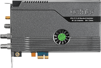
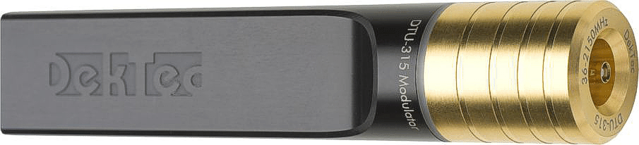
ATSC 3.0 Test Modulators
RF modulators that can modulate ATSC 3.0 (and various other modulation standards).
|
DTA-2115B All-standard VHF/UHF/L-band modulator for PCIe |
|
DTU-315 All-standard all-band modulator for USB-3 |
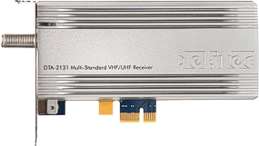
ATSC 3.0 Test Receivers
Receiver cards that can receive and analyze ATSC 3.0 (and various other modulation standards).
|
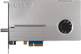
DTA-2131 1-channel cable/terrestrial SDR receiver for PCIe |
|
DTA-2139C 12-channel cable/terrestrial receiver for PCIe |
ATSC 3.0 Test & Measurement Software
Our industry-standard Test & Measurement applications, with complete support for ATSC 3.0.
 |
Atsc3Xpert ATSC 3.0 RF analysis |
 |
Atsc3Xpress ATSC 3.0 signal generation |
 |
StreamXpert ATSC 3.0 stream analysis |
 |
StreamXpress ATSC 3.0 playout |
ATSC 3.0 Transmission Workflow
The workflow in an ATSC 3.0 transmission system starts with an encoder with a built in DASH packager. This device takes in audio/video from SDI or IP sources and encodes them to HEVC video and Dolby AC4 audio. It then will package the encoded data into DASH segmented files of a certain length of time, typically 2 seconds.

Simplified block diagram of the workflow in an ATSC 3.0 transmitter system.
The encoder/packager actually sends a 2 second file for video, each audio, and captions to a folder in the next piece of equipment. That is a ROUTE server. The ROUTE server generates the signaling/LLS and ESG for the stream as well as takes in the DASH files from the encoder/packager and converts them to a unique ROUTE multicast for each service (including ESG). The signaling or LLS is also on a multicast, but it is not unique. This is mandated to be on 224.0.23.60:4937.
The ROUTE server sends the various multicast IP addresses on to the Broadcast Gateway. This device will aggregate the various ROUTE multicasts into another single multicast IP called an STLTP multicast. This multicast is determined by the user, and it contains all ROUTE service and the LLS. It also contains all the information the exciter needs to make the ModCod or set of modulation instructions.
The Issue
At Heartland Video Systems, Inc, we have now been part of over 25 ATSC 3.0 market transitions nationwide in the US and have provided setup, testing, and integration for these installs. We have had a full ATSC 3.0 lab for two years. In the lab, we are able to test encoder/packagers, ROUTE servers, Broadcast Gateway/Schedulers, exciters, consumer TV�s, and test equipment. We have every major manufacturer of each of those building blocks represented in our lab and can put them together in any combination we need to. Our goal is to be able to test out the equipment fully, from SDI or IP input to RF output, to make sure there are no issues or surprises when our customers launch the new ATSC 3.0 service.
This is very important because these market launches typically have all of the networks represented and they rely on the 3.0 Lighthouse station to make sure there are no issues. It has very high visibility and impacts many stations and groups, not just the one station that owns the ATSC 3.0 equipment. This is a larger scope than a typical install, where the only concern is with the station itself.
Heartland found that issues or questions will pop up after launch that will need attention. We identified a need to not only get a recorded output of the ATSC 3.0 signal for analysis, but also to play that out into our exciters and view the broadcast on our consumer TV�s or IRDs.
A few examples of the issues we have been looking into are video quality, signal signing (certificates), and content encryption (DRM).
The Goal
Using DekTec�s suite of ATSC 3.0 hardware and software, we can successfully play a PCAP file into our in house RF system and view the content on consumer devices like the Samsung, LG, and Sony NextGen TV�s, as well as on various test equipment like ATSC 3.0 analyzers and IRDs.
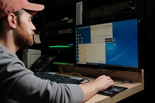
We have a server in house dedicated to the DekTec equipment. It has the ATSC 3.0 Receiver (DTA-2131) installed in a PCIe slot. We have a DekTec modulator (DTU-315) attached via a USB 3.0 connection. The DTU-315 output is connected to our lab's RF distribution system.

Lab setup for playing back ATSC 3.0 recorded in PCAP files.
It is very important to be able to feed RF into TVs and IRDs because some issues can�t be seen on an ATSC 3.0 analyzer. Any video or audio issue, for instance, would be hard to pick up if you were not decoding the A/V stream somehow to hear or see what the customer is reporting. We are also trying to verify the presence of certificates and DRM and, more importantly, to verify both work with consumer electronics without disrupting the viewing experience. The best way to address both is to play out a .pcap file in RF into our lab equipment and to our consumer TV�s.
Wireshark
WireShark is the program we use to capture .pcap files. You can download it from wireshark.org.
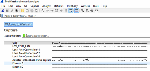
Wireshark lets you capture IP traffic in a .pcap file.
To record an ATSC 3.0 signal into .pcap file, you must use purpose built test equipment like an ATSC 3.0 analyzer, or you can use Wireshark installed on a laptop. The key is to be connected to the ROUTE or Broadcast Gateway/Scheduler STLTP output LAN so the Wireshark capture is seeing the ROUTE or STLTP multicast IP traffic. In this case, we have GigE_1 connected to an ROUTE LAN. Once you select the correct interface on your PC or laptop, just click the blue fin icon under File and start the recording. Capture about 2-4 minutes and save that file as a .pcap.
You will get a result that looks something like this:
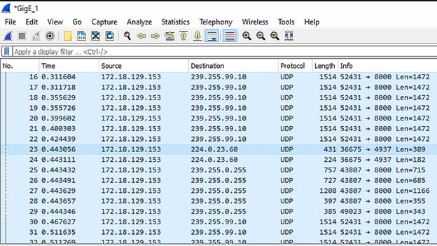
Wireshark capture of ATSC 3.0 network traffic.
You will notice a few different multicast IP addresses repeating.
- 224.0.23.60:4937 is the signaling or LLS multicast that is preset by the ROUTE equipment. This is going to be the same in every ATSC 3.0 signal. Perhaps it would help to relate it to the PAT always on PID 0 in ATSC 1.0.
- 239.255.0.255:8000 is the ESG service multicast. This contains all the guide info.
- 239.255.99.10:8000 is an A/V service ROUTE multicast. This multicast address will have been setup in the ROUTE equipment, it can be any multicast IP and would have been determined by whomever setup the equipment.
If you were on an STLTP LAN, the results would look very similar except you would only get one multicast IP and UDP port repeating. That would be the STLTP IP address that was setup in the Broadcast Gateway equipment.
The Steps
The first step is to get a pcap recording of an ROUTE or STLTP output. As mentioned above, try to make it 2-4 minutes so the downstream equipment has a chance to lock to the signal.
If you have an STLTP pcap, you can use StreamXpress to play that file format out natively. If you have a ROUTE pcap, then you will need to first convert it to an IQ file and then recreate your STLTP ModCod settings using the DekTec Atsc3Xpress.
Playback via ROUTE pcap
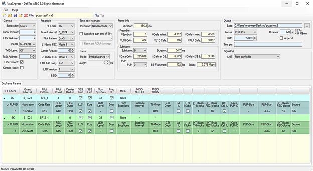
Below is an example of a 2-subframe/2-PLP signal we used in a market launch last year. This has a level of complication, because you need to recreate the exact ModCod settings you used on the customer equipment and enter them into the DekTec Atsc3Xpress. In many cases, settings names are different between manufacturers or may be missing altogether.
Atsc3Xpress generating a 2-subframe/2-PLP signal in an IQ file.
To playback via StreamXpress, we select the IQ file we made above as the source and the DekTec modulator (DTU-315) as the adapter to playout from. We chose the RF channel, IQ Modulation, and then hit play.
(Note from DekTec: Atsc3Xpress can also generate an RF output directly via the DTU-315 to the TV set without creating an I/Q file.)
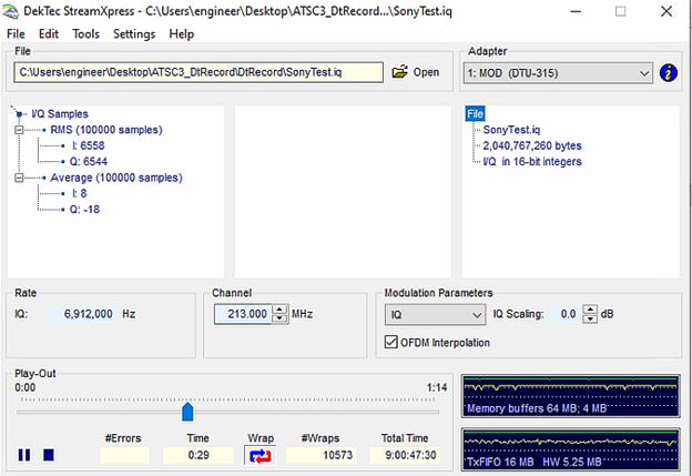
StreamXpress playing out an IQ file that was generated with Atsc3Xpress.
A warning, if the settings are not entered correctly or the ModCod is complicated enough to not be fully supported, you will have issues with reception. Because of this complexity, it might be best to get an STLTP capture and just use the next method supported in the newer versions of DekTtec software.
Playback via STLTP pcap
With the new software, we can now just jump into selecting the pcap file as the source and choose ATSC 3 STLTP for Modulation Parameters. We were able to see the stream on the DekTec analyzer StreamXpert (tied to the DTA-2131), the DekTec receiver software (also tied to the DTA-2131) and on all of our NextGen TV�s, just like we were at the station. This is a big step forward in our ability to understand and fix customer issues remotely.
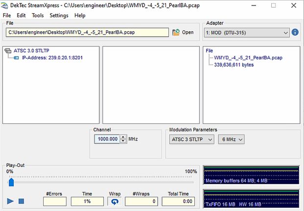
StreamXpress playing out an STLTP file that was generated with Atsc3Xpress.
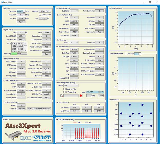
No matter the method (ROUTE or STLTP pcap) we can now see the output on the DekTec receiver (DTA-2131) using Atsc3Xpert. You are able to choose the subframe and look at each subframe and PLP.
Atsc3Xpert shows all L1 signaling info, RF graphs, and more.
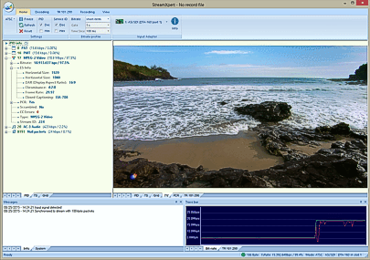
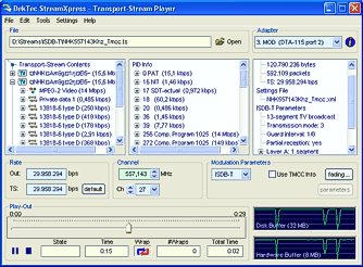
We can also use the StreamXpert analyzer to look at the content of the stream. Audio and video are decoded, and all ATSC 3.0 multicast streams are displayed fully decoded in a tree structure.
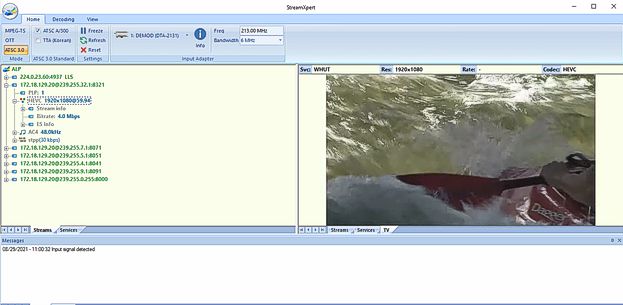
StreamXpert shows the content of the ATSC 3.0 stream.
This is now ready to play into consumer TV�s or IRDs for in depth analysis of the reported issue on the end-user platform.
This article was written by:
Mike Schmidt
Senior Systems Engineer
Heartland Video Systems, Inc.
1311 Pilgrim Road
Plymouth, WI 53073
800-332-7088
hvs-inc.com